Slobodan Midić
Here are represented three most commonly used MID wing airfoils in F1A free flights models:
* MID 102 N (wing root) * MID 102tip N (wing tip)
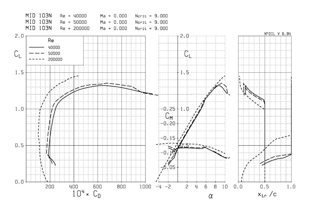
* MID 103 N (wing root) * MID 103tip N (wing tip)
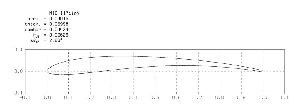
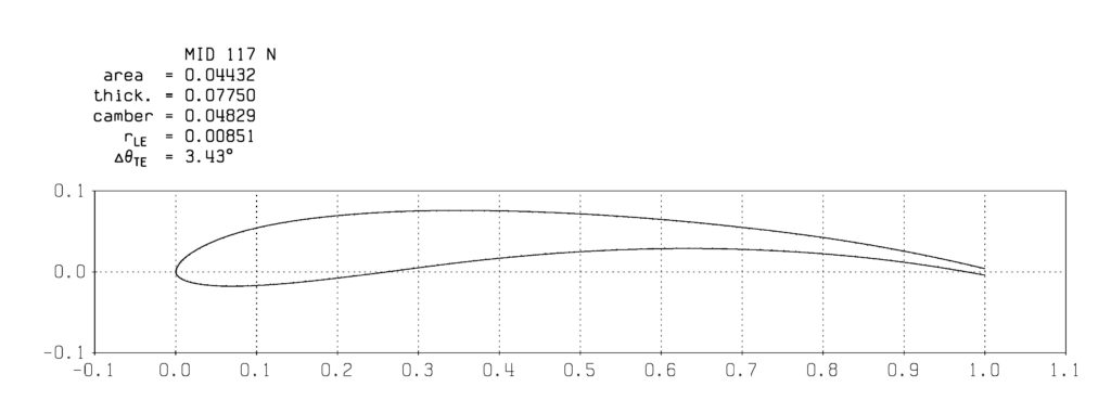
* MID 117 N (wing root) * MID 117tip N (wing tip)
The letter “N” in the airfoil designation means that the airfoils have been tested and redesigned, so small corrections have been made to the shape of the airfoil most around the nose and trailing edge. This resulted in better continuity of the polar lines of airfoil, without any peaks or discontinuities, so the airfoils are renewed.
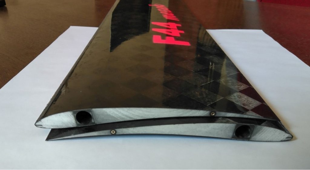
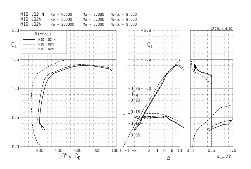
Since the F1A models are light, they fly at low speeds, so the air flow around the airfoil in free flight occurs in the critical field of transition from laminar to turbulent state. In order to prevent the spontaneous separation of the laminar boundary layer from the upper surface of the wing (which would lead to a sudden jump in air resistance during the movement of the profile), turbulators were applied to all these profiles on the upper surface of the wing at 50% of the wing chord, which forcefully transform the laminar air flow into turbulent, which allows the streamlines to reattach to the wing surface again but now as turbulent flow. Those turbulators are placed along the entire wing span and are usually 0.3-0.4mm thick nylon strings or 0.35×1.5mm plastic strips. Placing the turbulator closer to the leading edge increases the air drag in flight and reduces the finesse of the model, because then the model loses altitude more quickly. Without turbulators all above airfoils are very bad for flying as F1A wings.
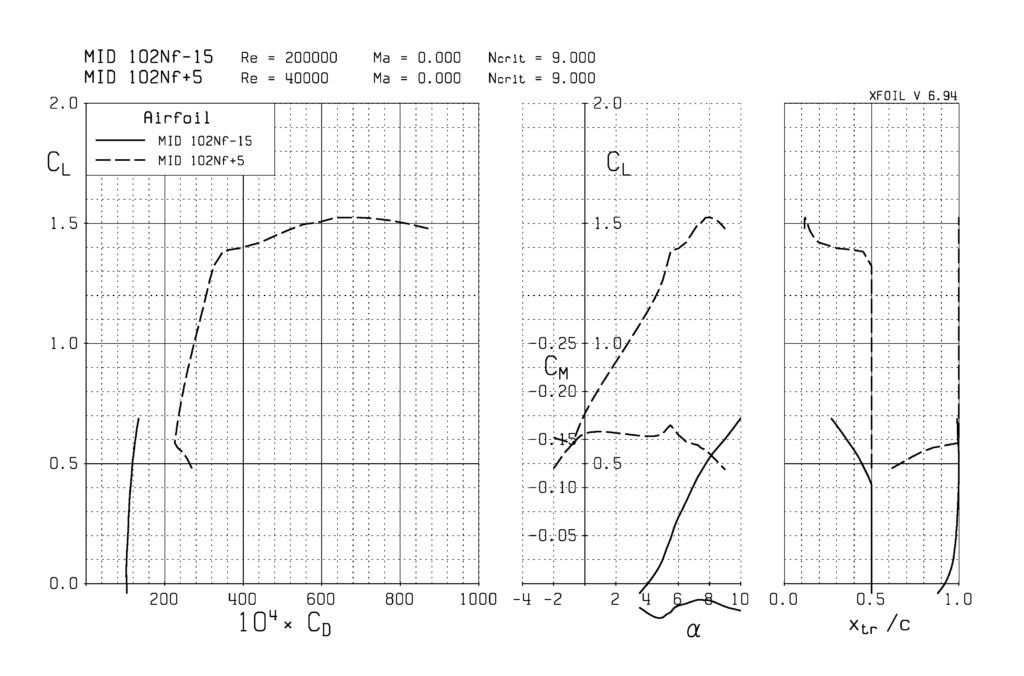
The Reynolds number characteristic of the air flow around the wing of the F1A model in steady gliding flight is Re=40000 and therefore for each profile for the F1A class of models a profile polar is given for that dimensionless number.
In addition, the profile polar is important for the Reynolds number Re=200000 or Re=200k, because it characterizes the profile for a vertical shot when ejecting the model from a 50m long towing rope, at a speed of 50m/s. A good indicator of the profile is that the polar has the as possible lowest drag coefficient Cdo at zero lift Cl=0.
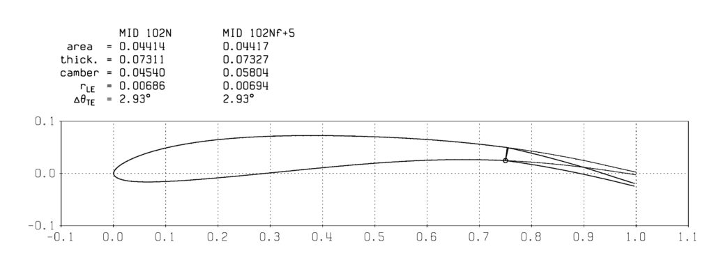
A further improvement in profile characteristics is achieved by making wings with flaps that can be deflected up and down to specific angles by means of suitable servos built into the wings (or less often in the fuselage). Flaps are actually rotating moving surfaces of the trailing edge of the airfoil, usually the width 25%-30% of the wing chord.
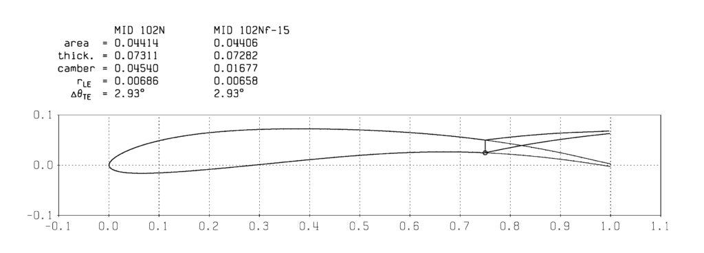
Flaps rotate around longitudinal wing hinges usually located on the lower surface of the wing. From the polar diagram of flapped airfoils, it can be seen that when the flap is deflected up by -15 degrees, the resistance of the profile Cdo at zero lift Cl=0 drops drastically to almost half of the value compared to the wing without flaps, which is used to achieve the highest possible height after releasing the model from the string during high start.
On the other hand, lowering the flaps down by a small angle, e.g. +5 degrees, the camber of the airfoil increases and the model climbs better in the thermal column of air.
In order to make good use of all those additional possibilities of flapped wings, a microprocessor timer must be used, which must be expertly programmed according to the existing weather conditions at that moment in the competition.
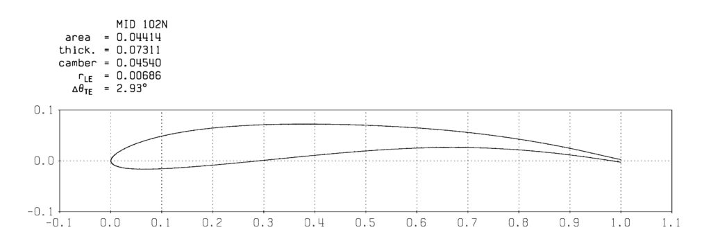
The main caracteristics of MID airfoils are given in the Table 1. and 2.

Koordinate MID 102 N
Koordinate MID 102 tip N


Koordinate MID 103 N

Koordinate MID 103 tip N


Koordinate MID 117 N

Koordinate MID 117 tip N